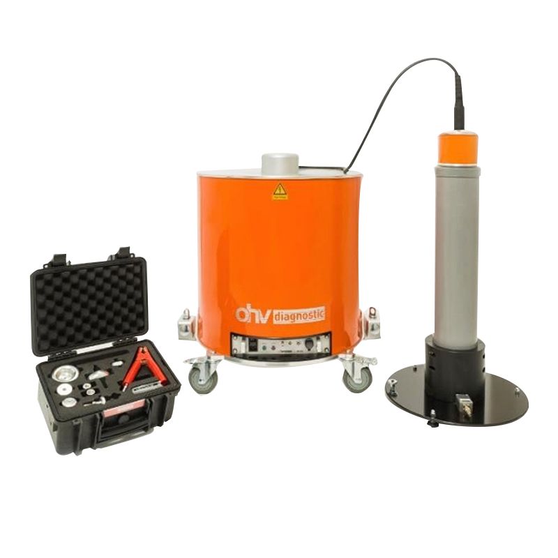
Cable Oscillating Wave Partial Discharge Tester

+ Free Shipping
SKU: HMJ9031 分类:

Product Overview

The Oscillating Wave Test System (also known as Damped Alternating Current, abbreviated as OWTS or DAC) is a specialized device designed for diagnosing the insulation condition of medium and high voltage power cables. By generating high-frequency damped oscillating waves, the system stimulates partial discharge (PD) at cable defect locations, enabling PD measurement and defect localization.

The DAC system supports both AC withstand testing and diagnostic measurements (including partial discharge and dielectric loss factor), providing reliable detection for common cable issues such as:

  1. Poor installation practices.
  2. Defects caused by improper cable laying.
  3. Defects within cable joints and terminations.
  4. Insulation aging and degradation of the cable body.


Features

Non-Destructive Testing

  • Traditional withstand voltage tests apply multiple times the operating voltage, which can damage the cable insulation. The oscillating wave test applies a controlled voltage peak (≤30 kV) with a short application duration (≤100 ms), minimizing the risk of secondary insulation damage.
  • Capable of measuring Partial Discharge Inception Voltage (PDIV) and Partial Discharge Extinction Voltage (PDEV) to assess defect activation thresholds.

Multi-Function Integration

  • Partial Discharge Detection: Range from 5 pC to 100 nC, compliant with IEC 60270 standards.
  • Dielectric Loss Measurement: From 0.1% to 10%, indicating insulation aging.
  • Capacitance Measurement: Range 0.025–4 μF, assisting in cable condition assessment.

Anti-Interference & Intelligent Analysis

  1. Auto bandwidth adjustment to filter environmental noise.
  2. Supports expert database for intelligent defect analysis, identifying types such as poor installation, joint defects, and insulation aging.


Technical Parameters

Item Specification
Maximum Output Voltage 30 kV (peak), 21.2 kV (RMS)
Minimum Output Voltage 3 kV (peak), 2.12 kV (RMS)
Rated Inductance 1.0 H
DAC Frequency 45–1000 Hz
Test Object Capacitance Range 0.025–4 μF
Power Supply 94–250V, 48–63Hz, 500VA
Sampling Rate 105 MS/s, 14 Bit
PD Detection Range 5 pC–100 nC
PD Integration Bandwidth 400 kHz (per IEC 60270)
Communication Protocol TCP/IP

This field is required.

Frequently Asked Questions about cable oscillating wave partial discharge tester

What is the cable oscillating wave partial discharge tester used for?

The cable oscillating wave partial discharge tester is designed for on-site cable insulation diagnosis, fault location and withstand testing. It is deployed in power cable commissioning, maintenance and fault repair, where it gives maintenance teams continuous or periodic visibility of insulation condition so that defects can be identified before they develop into unplanned outages.

What is the dac frequency of the this product?

According to the published specification, the dac frequency is 45–1000 Hz. This figure is measured under the reference conditions stated in the product datasheet; for project-specific acceptance criteria please refer to the type test report supplied with the quotation.

What does the test result tell me about the cable condition?

This product excites the cable and records the discharge activity as a function of the applied voltage. The key outputs are the partial discharge inception voltage, the discharge magnitude at test voltage, and — where a fault exists — the location of the discharge site or the fault itself along the cable. Comparing these values against the commissioning record and against previous tests is what supports a repair-or-continue decision.

How is the cable oscillating wave partial discharge tester powered and how does it communicate?

This product uses the following interface configuration: communication is TCP/IP; power supply is 94–250V, 48–63Hz, 500VA. This allows the same device to be fitted in both retrofitted installations and new builds; the exact combination is confirmed at order stage against the site communication architecture.

Is installation possible without an outage?

In most cases yes. Because the cable oscillating wave partial discharge tester is installed on the equipment while it remains energised, the work is normally carried out as a live-line operation by qualified personnel following the site safety rules. Where a sensor must be coupled to an earthed screen, bonded connection or gas compartment, a short outage may be required — this is confirmed during the site survey.

Does HUWOR support OEM/ODM and what is the delivery lead time?

Yes. Zhuhai Huawang Technology Co., Ltd. supplies the cable oscillating wave partial discharge tester under its own brand and also supports OEM/ODM supply, including private labelling, custom firmware functions and integration with the customer’s monitoring platform. Standard units are typically quoted with a lead time confirmed at order stage depending on quantity and configuration; sample and pilot orders are supported.

Applications

The cable oscillating wave partial discharge tester is used for on-site cable insulation diagnosis, fault location and withstand testing. Typical installation sites include power cable commissioning, maintenance and fault repair. It is applied both on new assets, where the monitoring function is built into the asset from the start, and on existing assets where it is retrofitted to extend the information available to the maintenance team.

How it works

The instrument converts the physical quantity of interest into an electrical signal, conditions and digitises that signal in the field unit, and passes the result to the monitoring platform or to the operator. Condition assessment relies on the trend rather than on a single reading: the value recorded today is compared with the commissioning value and with the historical series for the same measurement point, and it is the direction and rate of change that indicate whether the asset is degrading.

Installation and commissioning

Installation follows three steps: a site survey to confirm the mounting position, the communication path and the power arrangement; mechanical fitting of the sensor or the use of the instrument on the test point; and finally commissioning, where the readings are verified against a reference and the alarm thresholds are set.

For this model the relevant interface conditions are: communication TCP/IP, power supply 94–250V, 48–63Hz, 500VA.

Standards and documentation

Type test reports, calibration certificates and installation documentation are provided with the supply. Where a project requires the equipment to be verified against a specific national or utility standard, the applicable clauses should be stated in the enquiry so that the test scope can be confirmed at quotation stage.

评价

目前还没有评价

成为第一个“Cable Oscillating Wave Partial Discharge Tester” 的评价者

您的邮箱地址不会被公开。 必填项已用 * 标注

购物车