Introduction
Gas Insulated Switchgear (GIS) has become a key component in modern power systems due to its compact structure, high reliability, and excellent environmental resistance. However, the fully enclosed design of GIS also makes internal insulation diagnostics extremely challenging.
Among various insulation defects, partial discharge (PD) is widely recognized as an early indicator of insulation degradation and potential breakdown. Detecting PD alone is no longer sufficient for condition-based maintenance. What utilities and engineers truly need is the ability to identify the type of partial discharge source, so that the actual risk level can be evaluated correctly.
This article introduces a practical PD source identification method based on Ultra High Frequency (UHF) detection and time-domain waveform analysis, focusing on the relationship between discharge phase characteristics and rectified signal features.
Background: Challenges in GIS Partial Discharge Diagnosis
In GIS equipment, typical partial discharge sources include:
- Needle-shaped defects on conductors
- Floating metallic electrodes
- Surface discharges along spacers
- Free-moving metallic particles
Conventional PD diagnosis methods often rely on discharge magnitude or pulse count. However, these parameters alone cannot answer critical operational questions, such as:
- Is immediate shutdown required?
- Can the equipment continue operating safely?
- Is the defect stable or progressive?
Therefore, PD source classification becomes a crucial step toward meaningful insulation condition assessment.
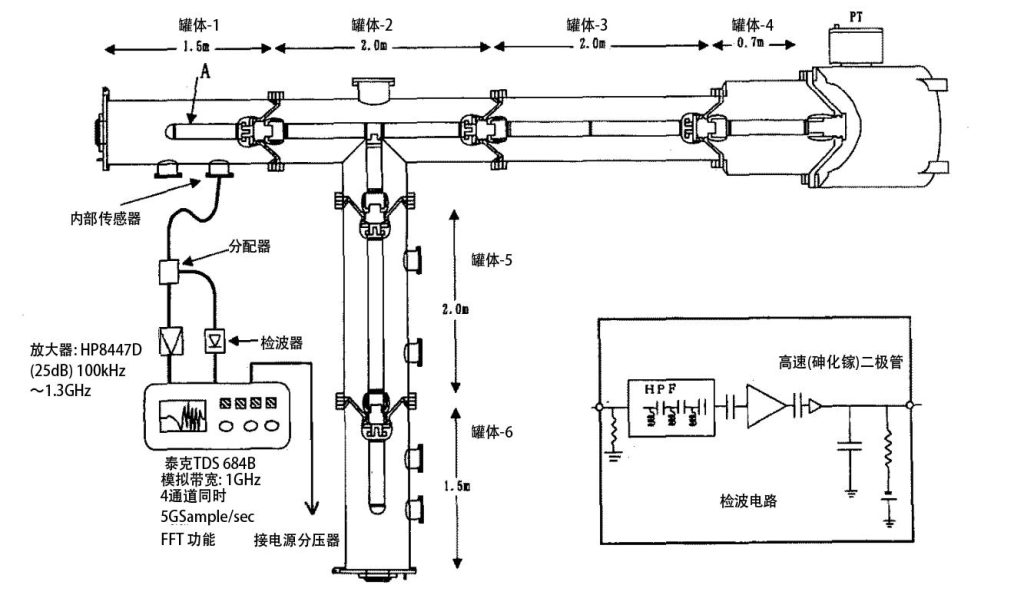
A 300 kV model gas insulated switchgear (GIS) used for partial discharge experiments. UHF sensors are installed on the GIS tank to capture electromagnetic signals generated by partial discharges. The measurement system includes a signal divider, high-speed amplifier, rectifier circuit, and oscilloscope for time-domain waveform analysis.
UHF-Based Partial Discharge Detection Principle
UHF PD detection is based on the fact that partial discharges generate extremely fast current pulses, exciting electromagnetic waves in the hundreds of MHz to GHz range. These signals propagate inside the GIS enclosure and can be captured by external UHF sensors.
Compared with conventional electrical PD measurement, the UHF method offers:
- Strong immunity to external electromagnetic noise
- Suitability for online monitoring
- Compatibility with PD localization techniques
By further analyzing UHF signals in the time domain, additional information about the physical discharge mechanism can be extracted.
Experimental Setup and Artificial PD Sources
A 300 kV model GIS was used to evaluate different types of partial discharge sources. UHF sensors with a bandwidth of approximately 200 MHz to 3 GHz were installed on the GIS tank.
Four representative artificial PD sources were introduced:
- Needle-to-tank discharge (sharp defect on conductor)
- Floating needle discharge (electrically floating metal electrode)
- Surface discharge on spacer
- Free metallic particle discharge
These defect types closely reflect real-world GIS insulation problems encountered in substations.
Phase Characteristics of Partial Discharge
By synchronizing the rectified UHF signal with the applied AC voltage, the phase distribution of partial discharges can be obtained.
The results show distinct phase patterns:
- Needle-to-tank discharge: occurs mainly near voltage peaks
- Surface discharge: concentrated around voltage zero crossings
- Floating electrode discharge: appears between peak and zero phase regions
- Free metallic particle discharge: weak correlation with voltage phase
These phase characteristics provide the first level of PD source differentiation.
Time-Domain Features of Rectified UHF Signals
To simplify signal processing, a high-speed analog rectifier was used instead of direct GHz waveform digitization. Two key parameters were extracted from each rectified waveform:
- Peak amplitude: related to discharge energy
- Half-width: representing the temporal development of the discharge
Relationship Between Peak Amplitude and Half-Width
When plotted in a two-dimensional feature space, different PD sources form distinct distribution regions:
- Needle-to-tank discharges show small amplitudes and narrow half-widths
- Floating electrode discharges exhibit larger amplitudes and wider distributions due to pre-discharge activity
- Surface discharges have relatively stable half-widths with varying amplitudes
- Free metallic particle discharges display large dispersion in both parameters
Although some overlap exists, combining these waveform features with phase characteristics enables reliable PD source identification.
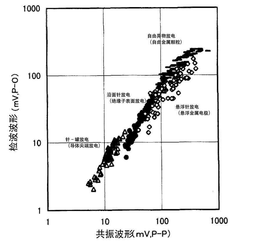
Comparison between the peak-to-peak amplitude of the UHF resonance waveform and the peak-to-zero amplitude of the rectified waveform. The linear relationship confirms that the rectification circuit preserves the characteristics of the original UHF signal without saturation.
Engineering Significance and Practical Application
The proposed identification method offers several practical advantages:
- No need for complex AI or deep learning algorithms
- Reduced hardware requirements compared to full GHz waveform processing
- Suitable for integration into online GIS monitoring systems
In practical applications, this method helps engineers:
- Distinguish between structural defects and contamination issues
- Assess insulation risk levels more accurately
- Support condition-based maintenance decisions
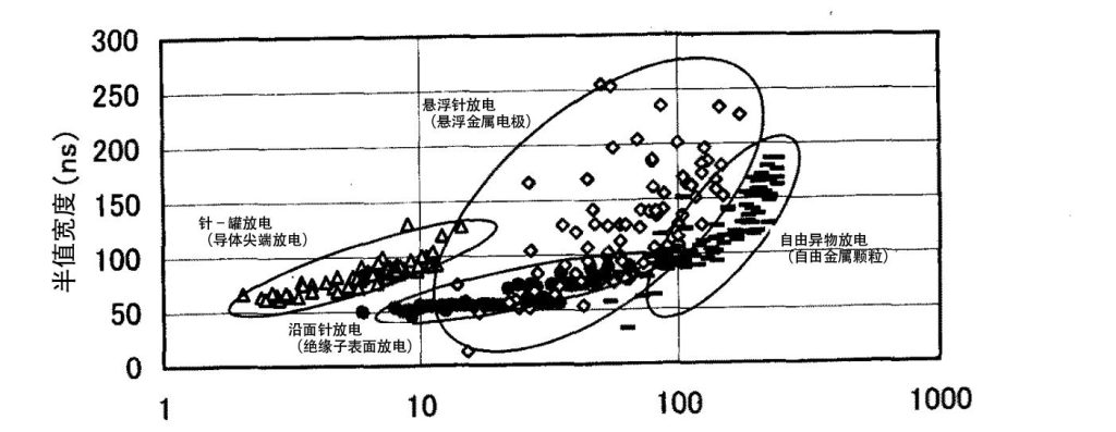
Scatter plot showing the relationship between the peak amplitude and half-width of rectified UHF signals for different partial discharge sources in GIS, including needle-to-tank discharge, floating electrode discharge, surface discharge on spacers, and free metallic particle discharge. Distinct clustering regions enable effective PD source identification.
Conclusion
UHF-based time-domain analysis provides an effective approach for identifying partial discharge sources in GIS. By combining voltage phase characteristics with rectified waveform peak amplitude and half-width, different PD mechanisms can be distinguished with high reliability.
This approach bridges the gap between PD detection and actionable insulation diagnosis, contributing to safer and more economical GIS operation.